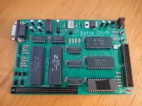
Baffa CP/M Single Board Computer
This project is based on "CP/M on breadboard" by Grant Searle. First, I've created an emulator to run the original files (ROM and CP/M) and after I've built a prototype to test my PCB version. For more information about Searle's original design, Rom files and CP/M System Files access his website. Many projects are using the BIOS, CP/M and MBasic versions written by him.
There is a Z80 CP/M SBC (single board computer) designed and compatible to Baffa-2 Peripheral Port. It has two port connections A and B for USB Serial connection and a RS232 connector attached to port B. Also, it can be expanded by connecting to Baffa Backplane to use boards compatible to Baffa-2 Homebrew Microcomputer.
Default Features:
- CPU: Z80 running at 7.3728 MHz
- Interface: Two high-speed serial ports up to 115200 Baud.
- Disk: 64MB or 128MB Compact Flash card support, containing 8 or 16 logical drives, respectively.
- RAM: 64KB or 512KB
- ROM: 16KB, switched off when CP/M active.
- Resets: Both cold (full reset) and warm reset (used to return to CP/M prompt) circuitry
- CP/M support: 2.2 with included software. More information about CP/M.
Single Board Computer
Related Files:
Firmware:
- ROM For Baffa CP/M SBC
- SDCard Image (128MB)
Represents 16 Disks from A to P
Other:
- CP/M Disk Manager
(read,manage and write SDCard Images) - CP/M Emulator written in C
- CP/M Programs
Bus Expansion Header
| Pin | Signal | Pin | Signal |
|---|---|---|---|
| 1 | A0 | 2 | A1 |
| 3 | A2 | 4 | A3 |
| 5 | A4 | 6 | A5 |
| 7 | A6 | 8 | A7 |
| 9 | A8 | 10 | A9 |
| 11 | A10 | 12 | A11 |
| 13 | A12 | 14 | A13 |
| 15 | A14 | 16 | A15 |
| 17 | - | 18 | - |
| 19 | !M1 | 20 | - |
| 21 | CLK | 22 | !INT |
| 23 | !MREQ | 24 | !WD |
| 25 | !RD | 26 | !IORQ |
| 27 | D0 | 28 | D1 |
| 29 | D2 | 30 | D3 |
| 31 | D4 | 32 | D5 |
| 33 | D6 | 34 | D7 |
| 35 | TX | 36 | RX |
| 37 | - | 38 | !RESET |
| 39 | GND | 40 | VCC |
| 41 | !RFSH | 42 | - |
| 43 | CLK2 | 44 | !BUSACK |
| 45 | !HALT | 46 | !BUSRQ |
| 47 | !WAIT | 48 | !NMI |
| 49 | - | 50 | - |
| 51 | - | 52 | - |
| 53 | - | 54 | - |
| 55 | - | 56 | - |
| 57 | TX2 | 58 | RX2 |
| 59 | - | 60 | - |
Settings
| CLK1 | ||
|---|---|---|
| = | SIO/SIO_A uses clk1 | |
| CLK2 | ||
| = | SIO/SIO_B uses clk2 | |
| CLK_A_EQ_B | ||
| = | SIO_A and SIO_B uses same clock | |
| JP1 | ||
| = | Internal Clock | |
| JP2 | ||
| = | Connect RTSB to RS232 | |
| = | Connect TXB to RS232 | |
| = | Connect RXB to RS232 | |
| JP5 | ||
| =o | SIO/0 | |
| o= | SIO/2 | |
| JP6 | ||
| =o | SIO/0 | |
| o= | SIO/2 | |
